
Instrumentation Cables
Instrumentation Cables
High Performance Shielded Cables for Precision Signal Transmission
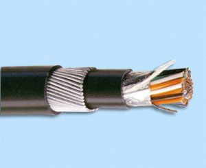
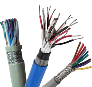
Vision International offers a comprehensive range of Aluminium Tape Screened and Copper Braid Shielded Instrumentation Cables designed for accurate signal transmission in critical environments. Available in both Armoured and Unarmoured formats, these cables provide excellent protection against capacitive and inductive interference generated by adjacent electrical fields.
Our instrumentation cables are widely used in Data Transmission, Automation Systems, Process Control and SCADA applications where signal integrity and reliability are essential.
Product Overview
We manufacture 300/500 Volt grade multicore and multi-pair instrumentation cables with:
-
Copper Conductors
-
PVC / XLPE Insulation
-
Individually & Overall Shielded Pairs
-
PVC Inner Sheath
-
GI Steel Wire / Strip Armouring
-
FR / FRLS Outer Sheathing
These cables are engineered to ensure stable transmission, minimal signal loss and long service life in demanding industrial environments.
Key Features
• Superior shielding against electromagnetic interference (EMI)
• Available in Armoured & Unarmoured versions
• Excellent noise rejection capability
• Suitable for indoor & outdoor installations
• High mechanical strength and durability
• Flame Retardant (FR / FRLS) options available
Construction Details
Conductor
Electrolytic Multistrand Bare / Tinned Copper conforming to IS 8130:1984
Insulation
XLPE
PVC Type A / Type C as per IS 5831:1984
Core Configuration
Available in Pair / Triad / Quad constructions
Pairing
Two insulated cores are uniformly twisted together forming a pair with a maximum lay length of 100 mm.
Pair Identification
Colour coded as per BS 5308 Part-2 standards.
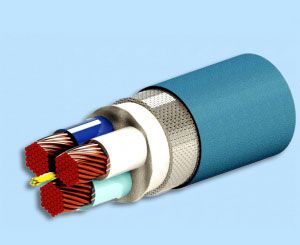
Shielding System
Individual Shielding
Each pair is shielded with aluminium mylar tape, helically applied with metallic side down and in continuous electrical contact with annealed tinned or bare copper drain wire.
Overall Shielding
All pairs collectively shielded with aluminium mylar tape, helically applied with metallic side down in continuous electrical contact with annealed tinned or bare copper drain wire.
Assembly
Twisted pairs are laid together with non-hygroscopic fillers where required to maintain shape and stability. All materials used are compatible with insulation to ensure long operational life.
Inner Sheath
Extruded or wrapped PVC inner sheath conforming to IS 1554 (Part-1).
Armouring
Galvanised flat strip or wire armouring as per IS 1554 (Part-1) for mechanical protection in harsh environments.
Applications
• Data Transmission Networks
• Industrial Automation Systems
• SCADA Systems
• Process Control Instrumentation
• Power Plants & Refineries
• Chemical & Petrochemical Industries
Colour Scheme/Code for
Identification of Pairs
| PAIR GROUP 1 | PAIR GROUP 2 | PAIR GROUP 3 | PAIR GROUP 4 | ||||||||
|---|---|---|---|---|---|---|---|---|---|---|---|
| Pair Ref. No | A-Wire | B-Wire | Pair Ref. No | A-Wire | B-Wire | Pair Ref. No | A-Wire | B-Wire | Pair Ref. No | A-Wire | B-Wire |
| 1 | White | Blue | 14 | Black | Braown | 27 | Red/Blue | Orange | 40 | Yellow/Blue | Grey |
| 2 | White | Orange | 15 | Black | Grey | 28 | Red/Blue | Green | 41 | White/Orange | Blue |
| 3 | White | Green | 16 | Black | Blue | 29 | Red/Blue | Brown | 42 | White/Orange | Orange |
| 4 | White | Brown | 17 | Yellow | Orange | 30 | Red/Blue | Grey | 43 | White/Orange | Green |
| 5 | White | Grey | 18 | Yellow | Green | 31 | Blue/Black | Blue | 44 | White/Orange | Brown |
| 6 | Red | Blue | 19 | Yellow | Brown | 32 | Blue/Black | Orange | 45 | White/Orange | Grey |
| 7 | Red | Orange | 20 | Yellow | Grey | 33 | Blue/Black | Green | 46 | Orange/Red | Blue |
| 8 | Red | Green | 21 | White-Blue | Blue | 34 | Blue/Black | Brown | 47 | Orange/Red | Orange |
| 9 | Red | Brown | 22 | White-Blue | Orange | 35 | Blue/Black | Grey | 48 | Orange/Red | Green |
| 10 | Red | Grey | 23 | White-Blue | Green | 36 | Yellow/Blue | Blue | 49 | Orange/Red | Brown |
| 11 | Black | Blue | 24 | White-Blue | Brown | 37 | Yellow/Blue | Orange | 50 | Orange/Red | Grey |
| 12 | Black | Orange | 25 | White-Blue | Grey | 38 | Yellow/Blue | Green | - | - | - |
| 13 | Black | Green | 26 | Red/Blue | Blue | 39 | Yellow/Blue | Brown | - | - | - |
Alternative Method of Identification of Cable Pairs
| Pair No. | A-Wire | B-Wire |
|---|---|---|
| 1 | White | Black |
| 2 to 50 | White with Number | Black with Number |
"PlATIMA"300/500V MULTIPAIR-COPPER PVC UNARMOURED -ARMOU RED (INDIVIDUAL & OVERALL SHIELDED)INSTRUMENTATION CABLES OF SIZE 0.50 SQMM (Ref. Spec. BS 5308 Part - 2)
| Size (Pair X mm²) | No. / Wire Diameter (No./mm) | Thickness of Insulation (Nom.) (mm) | UNARMOURED CABLE | ARMOURED CABLE | ||||||
|---|---|---|---|---|---|---|---|---|---|---|
| Outer Sheath (Nom.) (mm) | Overall Dia (Approx.) (mm) | Net Wt. (Kg/Km) | Inner Sheath (Nom.) (mm) | GI Wire/Strip Armour (Nom.) (mm) | Outer Sheath (Nom.) (mm) | Overall Dia (Approx.) (mm) | Net Wt. (Kg/Km) | |||
| 1 X 0.5 | 7/0.3 | 0.6 | 0.9 | 9.6 | 90 | 0.9 | 0.9 | 1.4 | 13.2 | 390 |
| 2 X 0.5 | 7/0.3 | 0.6 | 0.9 | 11.1 | 130 | 0.9 | 0.9 | 1.4 | 15.7 | 442 |
| 4 X 0.5 | 7/0.3 | 0.6 | 1.2 | 13.6 | 212 | 1.2 | 1.25 | 1.5 | 19.1 | 707 |
| 8 X 0.5 | 7/0.3 | 0.6 | 1.2 | 17.6 | 360 | 1.2 | 1.25 | 1.7 | 23.5 | 990 |
| 12 X 0.5 | 7/0.3 | 0.6 | 1.3 | 21.6 | 502 | 1.3 | 1.6/4X0.80 | 1.7 | 28.2 | 1454 |
| 16 X 0.5 | 7/0.3 | 0.6 | 22.9 | 22.9 | 629 | 1.3 | 1.6/4X0.80 | 1.7 | 29.5 | 1616 |
| 20 X 0.5 | 7/0.3 | 0.6 | 25.4 | 25.4 | 763 | 1.3 | 1.6/4X0.80 | 1.8 | 32.2 | 1864 |
| 24 X 0.5 | 7/0.3 | 0.6 | 28.9 | 28.9 | 936 | 1.5 | 1.6/4X0.80 | 1.9 | 35.9 | 2188 |
| 1 X 0.75 | 7/0.37 | 0.6 | 1.1 | 10.8 | 125 | 1.1 | 0.9 | 1.5 | 15.5 | 475 |
| 2 X 0.75 | 7/0.37 | 0.6 | 1.1 | 12.2 | 162 | 1.1 | 0.9 | 1.5 | 17 | 509 |
| 4 X 0.75 | 7/0.37 | 0.6 | 1.2 | 14.4 | 250 | 1.2 | 1.25 | 1.6 | 20.1 | 781 |
| 8 X 0.75 | 7/0.37 | 0.6 | 1.3 | 19 | 436 | 1.3 | 1.6X4X0.80 | 1.7 | 25.6 | 1268 |
| 12 X 0.75 | 7/0.37 | 0.6 | 1.5 | 23.5 | 618 | 1.5 | 1.6X4X0.80 | 1.8 | 30.3 | 1660 |
| 16 X 0.75 | 7/0.37 | 0.6 | 1.5 | 24.9 | 776 | 1.5 | 1.6X4X0.80 | 1.9 | 31.9 | 1869 |
| 20 X 0.75 | 7/0.37 | 0.6 | 1.7 | 28 | 968 | 1.7 | 2.0/4X0.80 | 2 | 36 | 2443 |
| 24 X 0.75 | 7/0.37 | 0.6 | 1.7 | 31.3 | 1150 | 1.7 | 2.0/4X0.80 | 2 | 39.3 | 2792 |
| 1 X 1.0 | 7/0.44 | 0.6 | 1.1 | 11.7 | 146 | 1.1 | 0.9 | 1.5 | 16.4 | 510 |
| 2 X 1.0 | 7/0.44 | 0.6 | 1.1 | 12.9 | 186 | 1.1 | 0.9 | 1.5 | 17.7 | 551 |
| 4 X 1.0 | 7/0.44 | 0.6 | 1.2 | 15.3 | 289 | 1.2 | 1.25 | 1.6 | 21 | 849 |
| 8 X 1.0 | 7/0.44 | 0.6 | 1.3 | 20.2 | 511 | 1.3 | 1.6/4X0.80 | 1.8 | 27 | 1419 |
| 12 X 1.0 | 7/0.44 | 0.6 | 25 | 25 | 728 | 1.5 | 1.6/4X0.80 | 1.9 | 32 | 1843 |
| 16 X 1.0 | 7/0.44 | 0.6 | 1.5 | 26.5 | 919 | 1.5 | 1.6/4X0.80 | 1.9 | 33.5 | 2074 |
| 20 X 1.0 | 7/0.44 | 0.6 | 30 | 30 | 1192 | 1.7 | 2.0/4X0.80 | 2 | 38 | 2750 |
| 24 X 1.0 | 7/0.44 | 0.6 | 2 | 34 | 1412 | 2 | 2.0/4X0.80 | 2.2 | 42.4 | 3226 |
Electrical Characteristics
| Conductor Size (mm²) | D.C. Resistance at 20°C (Ohm/Km) | Mutual Capacitance at 1KHz (nF/Km) | L/R Ratio (mH/Ohm) | |
|---|---|---|---|---|
| Pair Adjacent Core | Between any Core or Screen | |||
| 0.5 | 36.8 | 250 | 400 | 25 |
| 0.75 | 25 | 250 | 400 | 25 |
| 1 | 18.4 | 250 | 400 | 25 |
| 1.5 | 12.3 | 250 | 400 | 40 |
Note : The Conductor Size shall be According to the Resistance Value & it's Tolerance specified in IS:8130-1984
APPROVALS